MIL-STD-704 Power Standards for Aerospace Applications
Power reliability and consistency are critical factors in the operation of aerospace systems. To ensure system safety and performance, the United States Department of Defense established MIL-STD-704, a comprehensive power standard defining the characteristics of aircraft electrical power systems. This white paper provides a detailed analysis of MIL-STD-704, its power waveform specifications, application domains, testing protocols, and the role it plays in safeguarding avionics systems.
1.1 Origin and Purpose
MIL-STD-704 was introduced to define the electrical power characteristics of military aircraft. Its primary goal is to ensure that all electronic equipment functions properly and safely under defined power conditions. It governs AC and DC power characteristics, allowable transients, frequency variations, and power interruptions.
1.2 Scope and Relevance
Applicable to all military aircraft, MIL-STD-704 is widely adopted across defense platforms. Increasingly, it is referenced in civil aerospace and unmanned systems where military-grade reliability is essential.
2.1 AC Power Specifications
MIL-STD-704 specifies 115/200V, 400 Hz, three-phase AC power as standard for aircraft electrical systems. Key parameters include:
- Voltage Range: 108V to 125V (line-to-neutral)
- Frequency Range: 395 Hz to 405 Hz
- Total Harmonic Distortion: < 5%
Other variants include 60 Hz and wild-frequency (360 Hz to 800 Hz) systems.
2.2 DC Power Specifications
Two primary DC power standards:
- 28 VDC: Nominal voltage; range: 22V to 29V
- 270 VDC: Used in modern high-power platforms
DC systems require regulation, ripple control, and transient suppression.
3.1 Classification System
MIL-STD-704 defines waveform classes A through H, depending on voltage type (AC or DC), generation method, and system stability:
- Class A: Steady-state AC power (constant frequency)
- Class B: Variable-frequency AC
- Class D: Regulated 28 VDC
- Class F: 270 VDC systems
3.2 Voltage and Frequency Tolerances
Each class specifies limits on:
- Voltage deviations
- Frequency variation (AC)
- Transient response times
- Inrush current limits
This classification ensures predictability and performance across platforms.
4.1 Equipment Design Compliance
All onboard equipment must operate within MIL-STD-704 parameters. Design strategies include:
- Voltage regulators
- Filtering components (LC filters)
- Power conditioning modules
- Redundant power supply inputs
4.2 Load Compatibility
Power supplies must support varying loads without violating voltage/frequency specs. Equipment must handle:
- Power-up surges
- Steady-state consumption
- Transient spikes from switching events
5.1 Military Aircraft
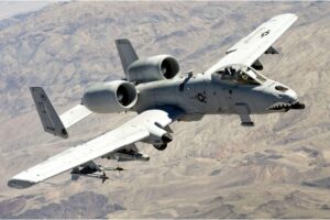
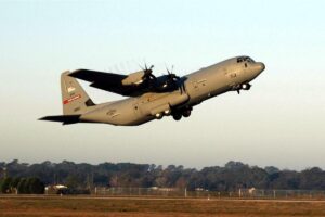
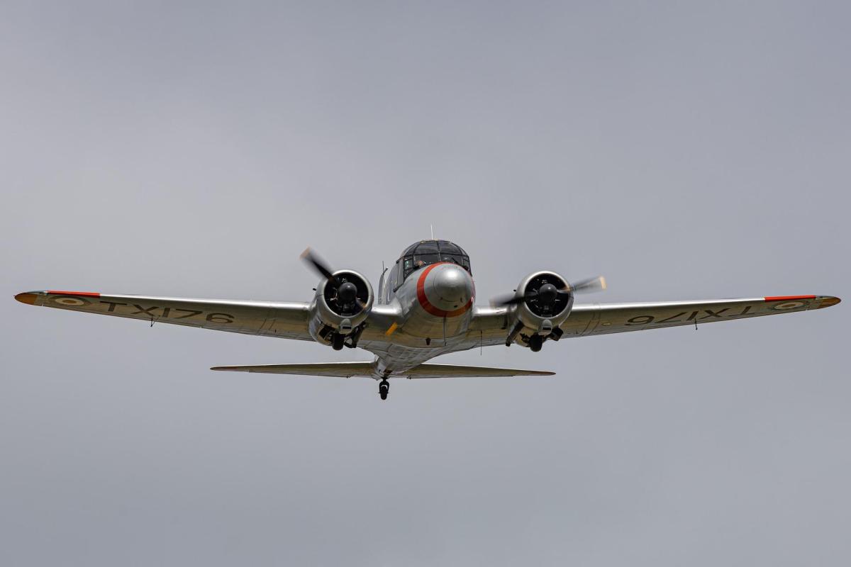
Fighter jets and transport aircraft rely on MIL-STD-704 for avionics, radar, EW systems, and weapon interface stability.
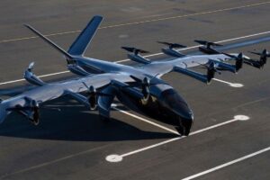
5.2 UAVs and Rotorcraft
Unmanned platforms benefit from the compact and reliable design enforced by MIL-STD-704.
5.3 Space Systems
Though not originally designed for space, MIL-STD-704’s robust characteristics have influenced spacecraft power bus design.
5.4 Naval and Ground Vehicles
MIL-STD-704-based systems are deployed in cross-domain military vehicles where airborne equipment is reused.
6.1 Test Equipment
Validation requires specialized tools:
- Power waveform simulators
- Transient generators
- Voltage and frequency monitors
- Programmable AC/DC sources
6.2 Test Procedures
Defined in MIL-HDBK-704, test methods include:
- Power interrupt and dropout tests
- Voltage surge and spike evaluation
- Frequency variation testing
- Ripple analysis
6.3 Pass/Fail Criteria
Criteria are based on:
- Voltage tolerance margins
- Time to recovery after transient
- Equipment functional integrity
7.1 Towards More Electric Aircraft (MEA)
Next-gen aircraft use more electric systems (e.g., electro-hydraulic actuators), requiring stable, high-power buses (270 VDC).
7.2 Integration with Other Standards
MIL-STD-704 must interface with:
- MIL-STD-461 (EMC)
- MIL-STD-1275 (vehicle power)
- DO-160 (civil avionics)
7.3 Hybrid Platforms
Civil/military hybrid platforms adopt MIL-STD-704 to ensure mission readiness and compatibility with defense subsystems.
8.1 Weight and Volume Constraints
Filtering and redundancy for compliance can increase equipment bulk.
8.2 Legacy System Upgrades
Modern 270 VDC systems must coexist with older 28 VDC avionics, requiring complex power architecture planning.
8.3 Environmental Factors
Extreme altitudes and temperature variations impact power stability and need to be accounted for.
- System reliability: Ensures consistent operation under all flight conditions
- Interoperability: Enables reuse of equipment across platforms
- Safety: Minimizes electrical failures
- Standardization: Simplifies certification and testing
MIL-STD-704 remains a cornerstone of aerospace power system design. From fighter jets to UAVs and hybrid aircraft, this standard ensures that every piece of electronic equipment operates within safe and predictable power parameters. As aircraft become increasingly electrified, understanding and implementing MIL-STD-704 remains vital to mission success.